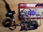
As I was working on the preliminary letterbox design, I noticed a fairly severe oversight. All of my experiments were based on a single display module, which an ESP8266 or ESP32 can handle easily using our chosen algorithm.
Adding additional display modules is going to change the game, however.
The core problem is one of power. The ESP32 can source or sink 30-40mA of current on any given GPIO. In our case, that’s not going to be enough; a single row could have as many as twenty-seven segments active at any given moment.
At only 2mA per segment we’re looking at 54mA, which means we’re going to blow the chip up. All of that current is going to be sunk by a single pin!
The Options
As I see it, the safe load to calculate for is probably in the neighborhood of 110mA. That’s around 4mA per segment, and gives us a bit of a margin of error so we can play with the resistor values and the like. Should be easy enough.
There are three basic options that I can see potential in:
Add drivers to the cathode pins to increase the capacity. This wouldn’t actually be that difficult, and is probably the most straightforward answer, albeit also one of the more expensive ones.
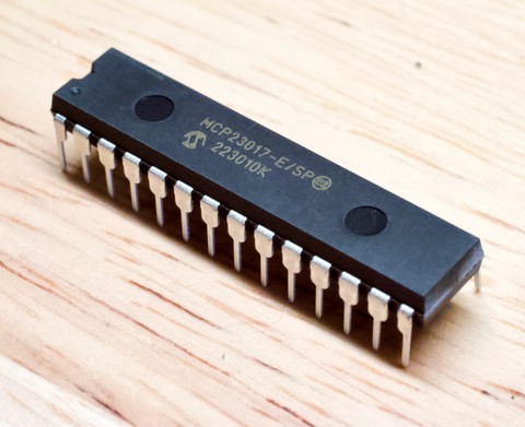
Add another GPIO extender or two and reduce the profile such that each cathode pin is sinking less current. The MCP23017 can only handle 25mA per pin, though, so that would limit us to around 2.7mA per segment.
Go a completely different direction. In this case, I’m considering shift registers. This makes sense for a number of reasons that I’ll get to in a moment – though it would end up as a sort-of combination of the above two methods.
Note that just adding more pins on the ESP is not going to work. We just don’t have enough available that are actually connected to the RTC power domain. The ULP can’t access most of the still-available pins.
The Driver Method
Dedicated Drivers
I considered going the dedicated-driver route (and Lumissil does have one that looks tailor-made for this project, the IS31FL3739), but it’s a lot more expensive than the other options. They have some neat features – PWM dimming and the like – but we can accomplish most of that in software using other methods, if not quite as cleanly.
Bottom line, though: it would double the cost almost. At Q100, each of these drivers is almost a buck fifty, and we would need one per display module. There has to be a cheaper way!
Generic Drivers
The simplest case is to throw a Darlington array on the outputs that handle the cathodes. One example would be this array, which would be nearly ideal I think. The cost would be reasonable, and it would only be one additional part.
Extend All The Things
If we add another couple of GPIO extenders, we can simply duplicate the cathode pins for each display; effectively, we dedicate a GPIO extender to each display module. This… is less than ideal due to the aforementioned current limits.
Not to mention the cost; those things are expensive, to the tune of $1.50 each if you look hard enough. Like the dedicated driver method, this is much more expensive than I would like.
Bits Gone Wild!
Too Good To Be True?
Now we arrive at the shift register method, which is where I’m currently leaning.
Admittedly, the power requirements aren’t the only reason I’m looking this direction. I have this strange idea of setting the thing up to work with Adafruit Feather Wings – but I need some free I/O on the ESP32 in order to do a decent job of that. As the (broken) design currently stands, all the analog pins are unavailable because the display is using them.
And it can’t be changed, because they have to be accessible from the ULP to meet our needs.
But what if we used fewer pins there? True, we can do that with the I/O extender method as well, but this method is a lot cheaper. Actually, it’s shockingly cheap.
Basically, we use a pair of 8-bit shift registers per display, similar to what we can do with the GPIO extenders. Even with the cheapest register I dug up with no effort – the Toshiba 74HC595D, we should be able to manage in the neighborhood of 4mA per segment.
Not too shabby for a chip that only cost around thirty cents. We would need six of ’em, for a total of $1.80. For the whole thing!
The Downside
Oh yes. There may be a downside.
When I initially thought about this, my intent was to just cascade the shift registers and stick ’em on the output of an SPI peripheral. It would make things very simple, wouldn’t it? It’s not that hard to shift 48 bits around.
Unfortunately, it won’t be that simple. Remember why I chose the MCP23017 initially?
Yup. There is no SPI in ULP-land!
This leads to a question: just how fast can we bit-bang this thing with the ULP? It’s unclear at best, though my research suggests it should be eminently doable. I calculate a minimum required toggle speed of only around 40KHz, so it should be easy.
Right?
Resetting Expectations…
Looks like I’m in a holding pattern now. I can continue to work on other aspects of the design, but I’m going to have to set up at least one more experiment. Specifically, just how fast can I bang bits out of a GPIO pin with the ULP? Is it fast enough to handle the shift register idea?
If it is, then it opens up some possibilities.
I really like the idea of being able to expand this thing by slapping a Feather wing on the back, but I/O is kinda needed there. My current use case is a good enough reason to build it, but the ability to add other toys to it could make it much more useful in the long run. Who knows what I would come up with?
Even if I end up not going down that path, however, there’s a strong probability that I’ll go with shift registers anyway, assuming I can get away with it. They’re about the same price as a single GPIO extender, and don’t need an additional driver.
I guess we’ll see what happens…
