Sometimes you sit down to work and realize that you should have stopped earlier the previous day. This was an example of one such day. I didn’t really notice it until I looked at the pulse trains in the images I published, but the timing was really screwed up in– well, everything.
That’s what I get for coding in my sleep.
Unfortunately, the fix really didn’t change much. The display was, as expected, still very dim in the per-segment mode. That got me thinking, though: just how bright are these LEDs when not being scanned? And just how much power are we actually using?
Enter a new “static” algorithm. Sure, we can only do one digit, but it’s good enough for measurements…
Static Values
So our experiment is running with 220-ohm resistors. A bit of probing with a multimeter with our static “F” on the display results in the following values:
| Item | Value |
|---|---|
| Voltage across limit resistor | 0.403V |
| Calculated Current | 1.8mA |
| Measured Current | 1.83mA |
Okay, that’s… surprisingly low, actually. The display under static conditions is extremely bright at that current level. And that leads one to wonder: just how much brighter would it be if we upped the current? Hmmm…
Of course, I did something very stupid yesterday: I attached the Saleae to the legs of my current limiting resistors. THAT is going to make things annoying, because I’ll have to reattach all those probes if I change them out…
In any event, halving the resistance should double the current, right? So 110 ohms would be around 3.6mA. The closest I have in my assortment are 100 or 120; so let’s go with 100. That would, by our calculations, net us 4mA. That sounds reasonable; it’s a fifth of the maximum the display is spec’d for.
So I change one resistor out just to eyeball it…
Yeah, not enough difference to matter. Strangely, it only netted us 3mA; The new voltage reading across that resistor is .310V.
WAT?
I ended up digging through various books, and found what I believe to be the answer in the Art of Electronics 3rd Edition X-Chapters book. Put simply, Vf is not a constant; there’s a curve relative to voltage or some such. Learn something new every day!
For an example, see this random datasheet from a Kingbright LED. On page 3, the third graph is “Forward Current vs. Forward Voltage”. Says it all, doesn’t it?
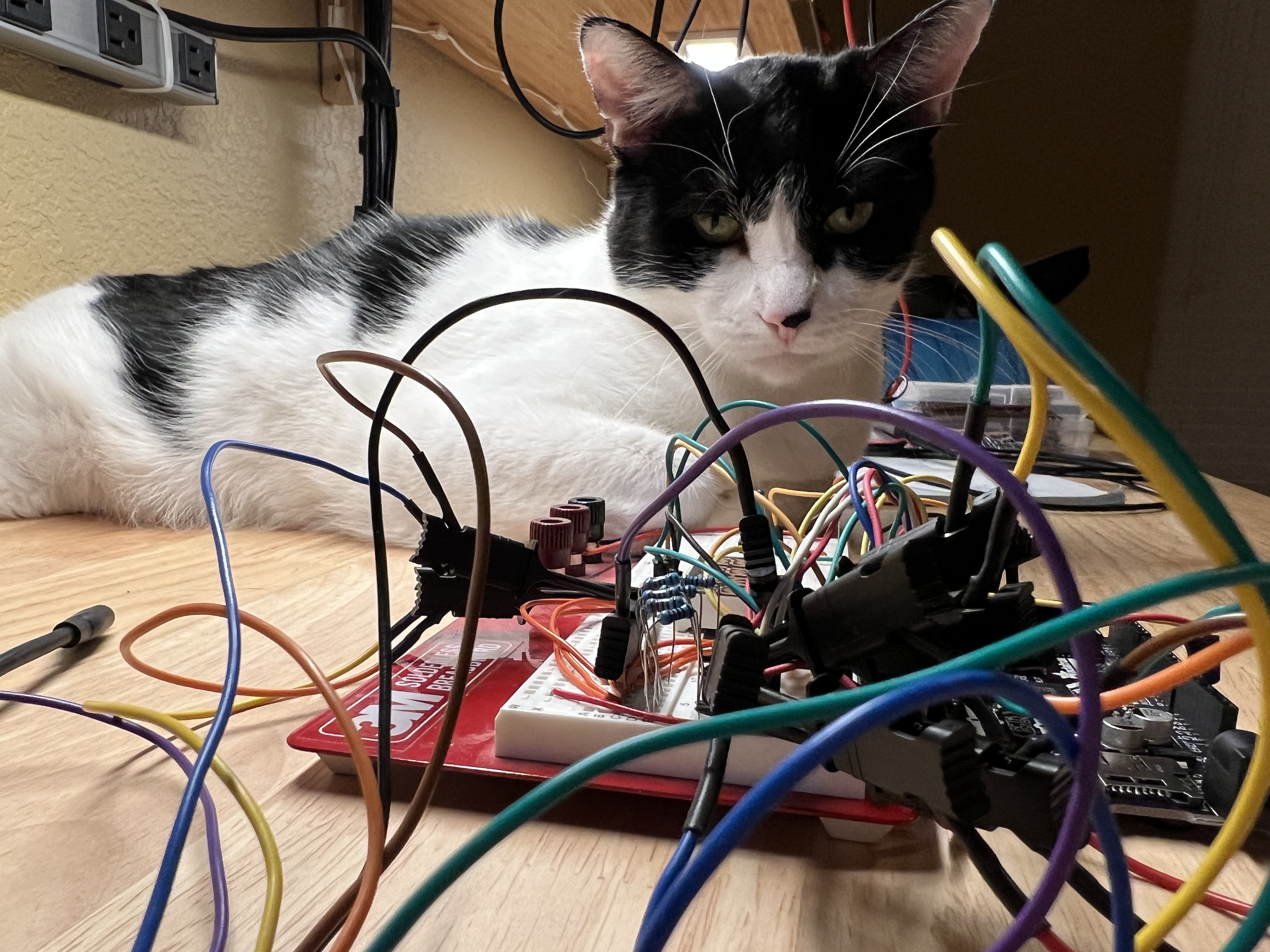
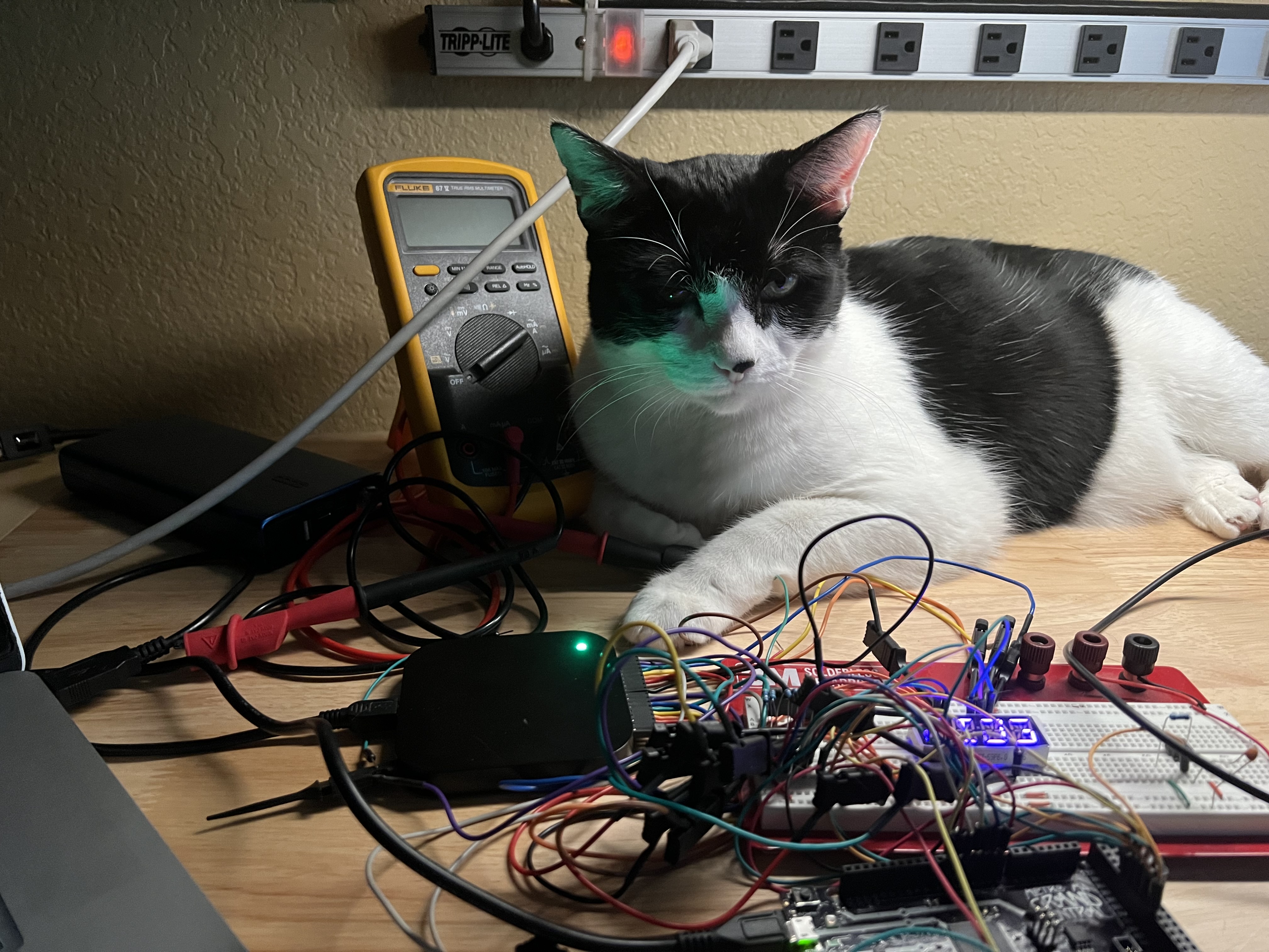
The modules I’m using lack this graph in the datasheet, so I’ll just have to do what I can with what I have. Now if you’ll excuse me for a moment, I need to go rescue my workshop from my cat. He’s found something to destroy (though thankfully not my current project!)…
Random Fixes
Moving right along…
I decided to just stick with the 220-ohm resistors for now; will think more about that later. Next up was cleaning up the GPIO transitions. That was simple enough; I now have some nice clean waveforms in all of the various modes. Or at least, as clean as I can make them. Everything seems to work.
Still hasn’t changed anything.
The Row Mode Issue
It turns out that the by-row algorithm, cleaned up or otherwise, is actually working as designed. The issue – the reason I’m seeing some segments shine more brightly than others – is because the hardware is not configured correctly to run this way – a fact that I missed in my initial thoughts on the subject.
We need the current limiting resistors on the anodes instead of the cathodes for that algorithm to work correctly, which is the opposite of how it’s currently built.
My current thought is to set up a second set of anode and cathode links connected to the Arduino; they can stay tri-stated if the algorithm is inactive – and the same for the existing pins if it’s active. That would let me switch between the modes. For this demo, that might be workable. It’s more work, though, so I’ll back-burner it for the moment.
In the mean time I reduced the demo to only having something to display on one character; this limits the current draw to only a single segment at a time, which will work fine with our current hardware and should give the correct result brightness-wise.
It’s a hair brighter than all the other algorithms. I’m not terribly surprised by that, honestly. That said, it’s also got a much higher potential current consumption when the hardware is configured correctly. With a 1.8mA-per-segment configuration on a 12-character display, you’re looking at a maximum draw of 43.2mA; if we go for the full 20mA specified in the datasheet, we get 480mA.
That’s a lot.
Current Measurements
Now it’s time to gather up data on how much current these various algorithms are using relative to each other. We will acknowledge that the by-row algorithm is currently incorrect; if I want accurate values, I will have to deal with the resistor configuration issue.
I also need to implement an “OFF” algorithm so we can get a baseline power number for the Grand Central itself. That’s easy enough, though.
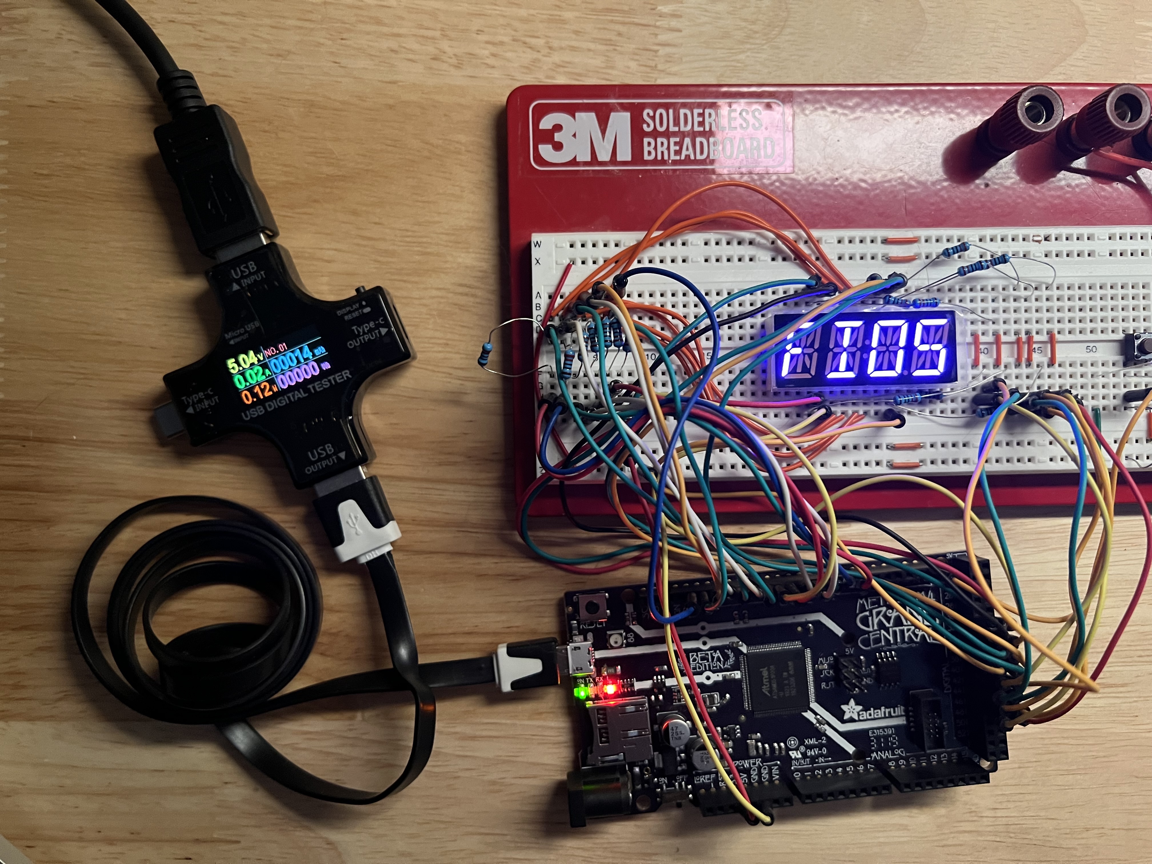
The power meter doesn’t have a whole lot of precision, but here’s what we’re seeing:
Baseline hovers around 20mA/.12W, though I believe that to be highly inaccurate. It often displays 0/0.
| Display String | Algorithm | Current Draw |
|---|---|---|
F | static | 30mA / 0.15W (steady) |
FIO1 | byseg | 20mA / 0.12W (bounces from 0 to this) |
FIO2 | byseg-permod | same as above (!) |
FIO3 | bydigit | ~same, peaking rarely at 30mA / 0.15W |
FIO4 | bydigit-permod | 30mA / .13W fairly steadily |
FIO5 | byrow | similar to above |
In the extremely short version, this tool is a bust. It’s not meant for measuring at any kind of high precision, and there’s also the fact that this is very spiky current use, so it may not catch everything. We’re getting only the peaks.
Maybe.
Seriously, even turning on as many segments as possible didn’t budge the needle. Part of that, I imagine, is that we’re heavily current-limited; the maximum current the existing setup can draw at any one time is approximately 12.6mA for the display (on top of the Grand Central itself). There’s simply no physical way for it to draw more than that.
This tool only reads amps to two decimal places. And doing our own metering setup would be a bear; I don’t have a USB breakout handy unfortunately.
Math will have to do.
I keep coming back to the by-row thing, though. I need to look at that.
Fixing The Rows
Fixing the current limit situation with the by-row algorithm turned out to be easier than I expected. After disconnecting the Saleae so I can work on the thing, I connected up secondary sets of anodes and cathodes, with another set of current limit resistors for the new cathode links. The software was easy enough to tweak to make it all fly.
I also documented it in the README; there’s no schematic, but the connections are explained, at least.
In the end, the by-row version is just slightly (but noticeably) brighter than the by-digit-per-module mechanism. That shouldn’t surprise me, really. If I have the math correct in my head, at the 1.8mA we’re running, the max utilization for the by-row algorithm is 1.8 x 12 x 2 = 43.2mA. For the by-digit on a per-module basis, it’s 1.8 x 7 x 3, or 37.8mA.
No matter what we do, brightness seems to follow energy consumption. Not that this is very surprising, all things considered…
The Data
So this is where I think we are with the various algorithms currently implemented in our little testbed (note that our current consumption is based on the actual 1.8mA draw per segment in the testbed):
| Algorithm | Max Draw | Status |
|---|---|---|
| by-seg-whole | 1.8mA | Way too dim to be useful. |
| by-seg-per-module | 5.4mA | A little brighter, but still way too dim. |
| by-digit-whole | 12.6mA | Much brighter, but still too little in direct light. |
| by-digit-per-module | 37.8mA | This appears to be workable. It’s a seemingly normal brightness. |
| by-row | 43.2mA | Ideal in terms of brightness, not so much in terms of max draw. |
Based on our current test strings (“FIO#”), here’s what I calculate for the actual peak draw in our testbed:
| Algorithm | String | Max Concurrent Segments | Max Draw |
|---|---|---|---|
| by-seg-whole | FIO1 | 1 | 1.8mA |
| by-seg-per-module | FIO2 | 3 | 5.4mA |
| by-digit-whole | FIO3 | 6 | 10.8mA |
| by-digit-per-module | FIO4 | 6 | 10.8mA |
| by-row | FIO5 | 4 | 7.2mA |
Hm. Isn’t THAT interesting? The by-row actually comes in under the by-digit. That makes it worth a lot more exploration, given that it comes in ahead of both of those algorithms for brightness. The question is, would that hold up once the rest of the display is introduced?
It seems to me that it’s all based on average usage. It simply depends on what we put on the display as to which one wins. For example, on a 12-char display, with every position filled with a single, particular character:
| Algorithm | Char | Max Concurrent Segments | Max Draw @1.8mA per | Average Draw |
|---|---|---|---|---|
| by-seg-whole | - | 1 | 1.8mA | ~0.26mA |
| by-seg-per-module | - | 3 | 5.4mA | ~0.78mA |
| by-digit-whole | - | 1 | 1.8mA | 1.8mA |
| by-digit-per-module | - | 3 | 5.4mA | 5.4mA |
| by-row | - | 12 | 21.6mA | ~6.2mA |
Now THAT is a difference in peak utilization, isn’t it? Note the average, though; that was calculated by taking the calculated draw of each scan step and then averaging it out. The numbers change a bit, don’t they?
Now what happens with a more “active” character?
| Algorithm | Char | Max Concurrent Segments | Max Draw @1.8mA per | Average Draw |
|---|---|---|---|---|
| by-seg-whole | * | 1 | 1.8mA | ~0.26mA |
| by-seg-per-module | * | 3 | 5.4mA | ~0.78mA |
| by-digit-whole | * | 7 | 12.6mA | ~7.2mA |
| by-digit-per-module | * | 7 | 37.8mA | ~21.6mA |
| by-row | * | 24 | 43.2mA | ~25mA |
And how about a more “normal” character?
| Algorithm | Char | Max Concurrent Segments | Max Draw @1.8mA per | Average Draw |
|---|---|---|---|---|
| by-seg-whole | A | 1 | 1.8mA | ~0.26mA |
| by-seg-per-module | A | 3 | 5.4mA | ~0.78mA |
| by-digit-whole | A | 6 | 10.8mA | ~6.3mA |
| by-digit-per-module | A | 6 | 32.4mA | ~18.9mA |
| by-row | A | 24 | 43.2mA | ~21.6mA |
I really need to write some code to check these numbers or something to ensure that my math is accurate, but it feels right at least. The bottom line is that the by-row isn’t likely to be nearly as expensive as it appears once you average out the usage.
Added to Round 3:
- Work up a simulator that will work out max/average current draw for a given message for each of the algorithms. Run tests and see what the likely outcome is for each algorithm. Determine whether there is a case for adaptive alogrithms – where which algorithm is best depends on the message to be displayed…
Various Thoughts
The by-row algorithm definitely has the nicest look, and the power requirements don’t actually appear to be all that prohibitive. Looking at the FIO messages, it could even be better if my analysis was correct there (which I’m not convinced of since it was mostly done in my head).
It also has the advantage of making it exceedingly easy to maintain a consistent brightness over the entire display. There isn’t really any way to vary it; the only potential optimization is to skip over a cathode that has no active segments attached for whatever is on the display. That’s actually a fairly unlikely scenario though IMO, and not really worth pursuing.
On the other hand, if we dim the display down at night or something, the by-segment mechanisms are far cheaper energy-wise. There could be an argument there.
This is going to have to be analyzed out. I think I mentioned in my previous post that I have logs of all the things that were sent to the boredom display; I think I might grab those, filter out anything with non-ASCII in it, and put it through a program to calculate out average current usage for each algorithm with the first twelve characters of a given message.
That should be informative, no?
There’s also the thought of optimizing the OTHER algorithms, most notably the per-segment algorithm. That one has potential, especially if we’re in an adaptive scenario where we can switch to another algorithm if needed. Power savings is the name of the game here, and being able to operate the display with a hard upper bound of, say, 1.8mA? That has potential if it competes favorably with the by-row methodology.
Many things to consider…
More tomorrow, I hope. It’s Easter, though, so maybe not. We’ll see…