
Display power consumption is going to be a problem for the LetterBox. Today’s project is to tinker with one of my newly-acquired displays and see what exactly I can get away with in terms of consumption. This will inform the rest of the design, most notably just how small we can get away with making this thing.
Batteries are fairly large…
I have a number of different potential scan algorithms in mind. The easiest way to prove which one is going to be best – and get the associated power consumption numbers for future design purposes – is to build a little toy to test it. The issue is that we’re effectively solving for brightness vs. power consumption, and the former is a fairly subjective measure.
For once, I’m actually writing up the experiment ahead of time. Go me!
The Algorithms
There are a number of ways to scan the displays, and each has pros and cons. Different scan rates, different duty cycles… and different average power consumption, most likley. The following are the algorithms I’ve come up with so far:
By Segment (Whole Display)
 In this algorithm, the 12-character display is scanned as 168
individual segments (I’m ignoring the decimal points and colons for
the sake of this investigation). Basically, we loop through every
single segment in the display, with only one segment ever being active
at a time.
In this algorithm, the 12-character display is scanned as 168
individual segments (I’m ignoring the decimal points and colons for
the sake of this investigation). Basically, we loop through every
single segment in the display, with only one segment ever being active
at a time.
Given that the continuous forward current specified in the display’s datasheet is 20mA, then 20mA is our maximum consumption at any given time. How much lower than that it will be depends on how far we can current-limit the display without reducing brightness too much.
The downside here that each segment will have a much lower duty cycle than with other methods. A simple calculation comes up with each segment having somewhere in the neighborhood of 6ms of “on time” per second.
That doesn’t seem right to me – my math could be wrong – but I think it’s correct. And if it is correct, it’s not much. That means that this is likely to result in a very dim display, but we’ll see…
By Segment (Per Module)
 This is almost identical to the above, except that three
four-character display modules are scanned simultaneously. This
results in only 56 segments scanned in a given second, for a maximum
on-time per segment of around 18ms. Better, but still a fairly small
value.
This is almost identical to the above, except that three
four-character display modules are scanned simultaneously. This
results in only 56 segments scanned in a given second, for a maximum
on-time per segment of around 18ms. Better, but still a fairly small
value.
The maximum continuous current consumption on a 12-digit display triples compared to the full-display version, so around 60mA.
By Digit
 This would be a per-character scan, where all segments in a character
are handled simultaneously (or rather, in two scan steps since each
character has two groups of common-anode segments on this display).
In this case, you’re only scanning each half of the 12 characters, so
24 scan steps. That leaves us with around 42ms on-time per second.
This would be a per-character scan, where all segments in a character
are handled simultaneously (or rather, in two scan steps since each
character has two groups of common-anode segments on this display).
In this case, you’re only scanning each half of the 12 characters, so
24 scan steps. That leaves us with around 42ms on-time per second.
That’s a much longer on-time, but it comes at a cost: You can have up to 7 segments active simultaneously, raising the maximum continuous current to 140mA, which is a very large increase.
Sadly, this is one of the most likely candidates for a readable display in my opinion, though we’ll see what the test proves. I will also note that we could do a “per module” variant of this as well for a very bright display, but that would bump the current consumption to 420mA, which is far too high in my opinion.
At that point, we would have to reduce the per-segment current substantially (which is not at all impossible, and in fact might be quite likely in the end).
By “Row”
 This is similar to the digit scenario, but works a little differently.
Rather than set the segments and energize an anode, we set the anodes
and energize a segment. Effectively, if this were a bar graph instead
of a 14-character display, we would be literally scanning by rows instead
of columns.
This is similar to the digit scenario, but works a little differently.
Rather than set the segments and energize an anode, we set the anodes
and energize a segment. Effectively, if this were a bar graph instead
of a 14-character display, we would be literally scanning by rows instead
of columns.
Where scanning by digit happens in twelve steps, this happens in seven – one for each segment in a group (don’t forget, we have two groups of common-anode-connected segments per character). The timing therefore works out to around 143ms on-time per segment.
Like the previous group, this comes at a cost: the maximum number of simultaneously lit segments is 24, which gives a maximum current consumption of 480mA; this is the most power-hungry of all our algorithms. I will note that you would halve that by doing two scan steps (one per segment group), but would also reduce us to just north of 70ms on-time.
Random Thoughts
There are a number of variations on each of the above scan algorithms. Additionally, the maximum continuous current numbers are based on a 20mA continuous current per segment, which is quite probably too high, though time will tell on that score. That’s the whole point of the experiment; let’s find what algorithm gives us reasonable brightness, then tinker with the current levels and re-test. Or thereabouts.
Basically, we’re going to find a good balance of scan algorithm to current limits that gives us the best display we can manage with the least power used.
A couple of other notes:
These algorithms have all been designed to ensure uniform brightness, regardless of what letter is displayed. This is currently done through strict time-slicing; if a segment is off, it will still consume the time where it is potentially lit, but will not be lit. Effectively, the display will be off for a while. That has interesting implications for power utilization comparisons in addition to–
The power numbers do not take into account the average display usage. In normal usage, some characters will be blank, and many segments will not be active, which will reduce the actual consumption by quite a lot. It might be worth investigating; I have a log of every message that has hit the Boredom display, and it might be neat to know what the average number of lit segments is, etc.
None of this takes into account the maximum limits of whatever microcontroller is chosen to drive this thing in the end. That will also impose its own limits; this experiment will significantly inform that selection.
There are various optimizations that can occur; for example, taking into account “off” segments and stretching “on” times accordingly to increase brightness rather than maintaining strict time slices. That has other potential issues as well, however.
One of the typical hacks is to use a higher “pulse current” than the LEDs expect for continuous use. This can make for a brighter but shorter-duration pulse, thus aiding in brightness. Unfortunately, while most LED modules seem to specify the maximum pulse current (and maybe duration), this unit is not one of them. I get specs for continuous current, and that’s it. In the interest of not destroying my modules, I’m going to avoid overdriving them for now, deliberately or otherwise.
Experiment Setup
Setup is simple enough:
 Will use an Adafruit Grand Central M4 that I have lying around.
It’s 3.3V (which our target env will likely be as well), and with a
SAMD51 processor, fast enough to handle whatever we throw at it.
it also works with Arduino, which will make programming a simple
matter (CircuitPython? Just say no!).
Will use an Adafruit Grand Central M4 that I have lying around.
It’s 3.3V (which our target env will likely be as well), and with a
SAMD51 processor, fast enough to handle whatever we throw at it.
it also works with Arduino, which will make programming a simple
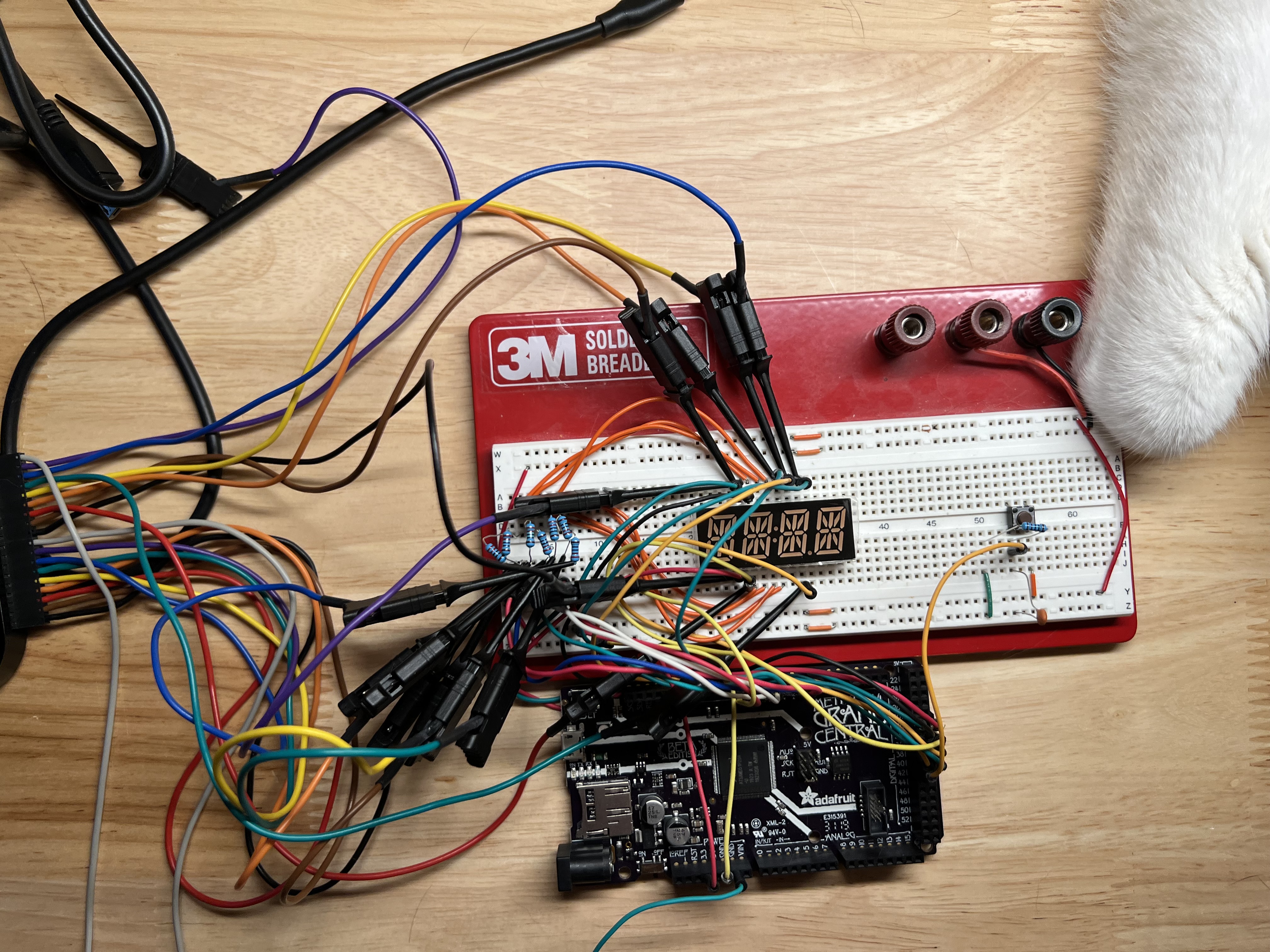
matter (CircuitPython? Just say no!).Hardware will be a single 4-character display unit, fully wired (excepting colon and decimal, which I honestly don’t care about for this). 220-ohm current limiting resistors on each segment cathode to start. Also a button with a capacitor-based hardware debounce.
Sketch will be written that will perform each of the above algorithms. Switching between them can be accomplished by pressing the button, allowing quick side-by-side comparisons of the algorithm results.
Easy, right? For now, the goal is to see which one produces the brightest display, and check some of our assumptions on power consumption. We’ll see where it goes from there. If we find a clear winner, we’ll tweak the current limit resistors until we have something that looks good – and then compare it again against the other algorithms.
Other Notes:
The SAMD51 datasheet says 8mA max output on a GPIO. That might limit us a bit (or I might destroy the chip; we’ll see). At 220 ohms, I would expect the current to be limited to around 2.7mA per segment. Need to verify the forward voltage of the LEDs in the unit, however, and thus the voltage across that limit resistor, so we can get correct current calculations.
Wiring will start at pin 0 on the Grand Central for segment cathodes, and pin 30 for segment group anodes.
And off to wire it up and code I go…
Round One
I spent a fair amount of time over the last couple of days putting the basics together. Not that hard, really; it’s not like Arduinos are hard to use, and I already have all the nifties to make it all work. Of course, nothing is ever as easy as it sounds.
Early results:
Per segment, whether single or parallel by module, is readable in low light, but far too dim in average ambient room light.
Per digit is actually pretty readable, but not quite at the level I would like. That can quite probably be solved by adjusting the limit resistors, but I was hoping for better.
My implementation of per-digit, parallel by module, seems broken. It makes no discernable difference to the brightness, which seems wrong somehow.
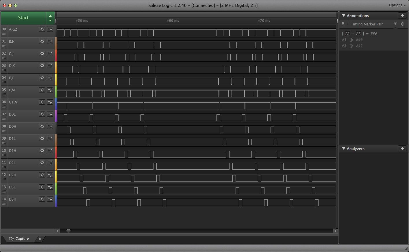
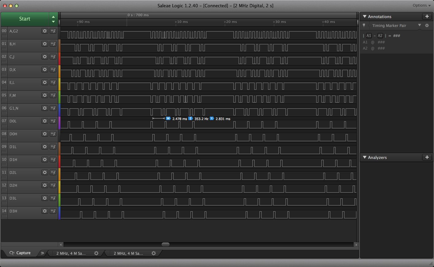
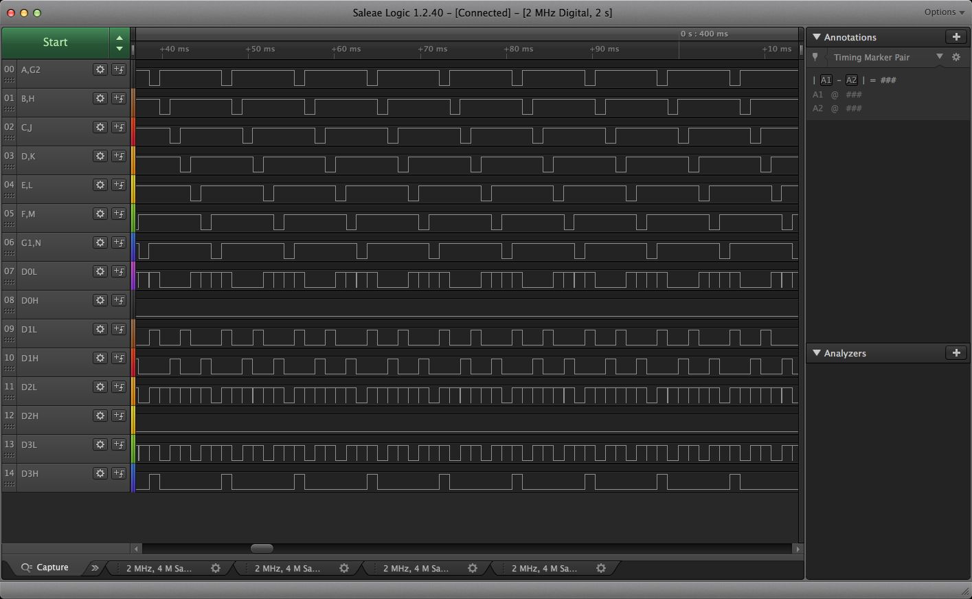
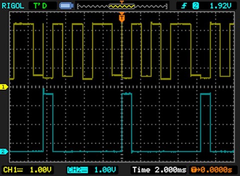
Something to look into.UPDATE: Yeah, it was broken, or rather my “whole display” version was. It wasn’t delaying bewteen runs like it was supposed to to simulate the missing digits. I still think the delay is too short, but as you can see in the screenshots above, it’s at least closer to correct now.The per-row algorithm is… underwhelming, and frankly looks wrong. I’m pretty sure I messed up somewhere in the implementation, or some segments wouldn’t be brighter than others. I’m going to have to revisit that one, which is not really a surprise; I was half asleep when I wrote it.
 I
actually bothered to hook it up to my oscilloscope (yay for actually
having a dedicated workshop!), and the
waveforms generated by my code are very dirty. I whipped up the
algorithms in the quickest “correct” way possible for a programmer,
without taking into account the effects of extra GPIO twiddling on
things like the produced waveforms. That will need to be cleaned
up, if only so it stops bugging me. It’s technically correct (I
think) after a fashion (except maybe the broken per-row
algorithm), but does a lot of extraneous pin wiggling that it really
doesn’t need to do.
I
actually bothered to hook it up to my oscilloscope (yay for actually
having a dedicated workshop!), and the
waveforms generated by my code are very dirty. I whipped up the
algorithms in the quickest “correct” way possible for a programmer,
without taking into account the effects of extra GPIO twiddling on
things like the produced waveforms. That will need to be cleaned
up, if only so it stops bugging me. It’s technically correct (I
think) after a fashion (except maybe the broken per-row
algorithm), but does a lot of extraneous pin wiggling that it really
doesn’t need to do.

I also pulled out my old Saleae Logic 16 and hooked it up to the relevant signals so I can see the overall algorithms in action (hence the images above in the algorithm descriptions). When I went to download the software, I was shocked to discover that a 16-channel Saleae is now in the $1500 range. I paid $294.95 for mine from Adafruit back in June of 2012! How in the heck do they justify a 5x price increase in that time?!
Glad I’ve got one already; their 8-channel “non-pro” unit is $500! Granted, they’ve improved the product – it’s safe to 25V and a few other nice things – but still!
But I digress…
I also realized that I have no good way of measuring power consumption, so I put an order in for a cheapie USB power meter that should get here later today. Love or hate Amazon, that you can get something like that with same-day service is fairly amazing.

And that leads to my main goals for round 2:
- Clean up the waveform generation
Verify that the parallel module version of the per-segment algorithm is working correctly. I’m not convinced.(I was right; now I just need to tweak the timing possibly.)- Figure out what’s wrong with the per-row algorithm and fix it.
- Measure and document the results.
- Maybe tweak the current limiting resistors and see where we get.
I’m also already starting a pile of goals for round 3:
- Look at the effects of optimizing out dead cycles (where no segments are lit). This would especially affect the per-segment algorithms, which could easily change the game.
That last one is of significant interest to me. First things first, though; we need to be dealing with a sane, clean set of algorithms that work roughly the way they would in an actual well-engineered product.
And so I wander off to start working on that. I might just publish this and write a new post for round two… Actually, yeah. That’ll get it off my mind so I can start on a whole new build log. =)
This one has gotten a little long and rambly…
