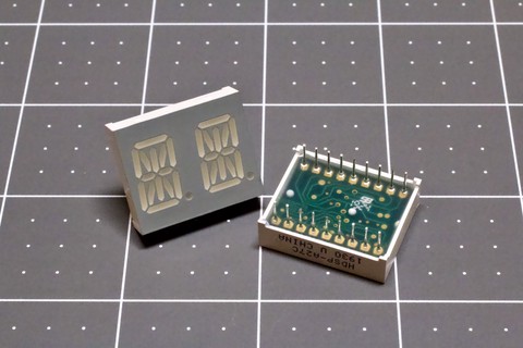
I’ve long held a certain fascination with old-technology displays. There’s just something special about them. Notable on the list is the 14-segment alphanumeric variety.
These displays are very similar to the ubiquitous 7-segment numerics, if a bit less common. Basically, you take a typical 7-segment display, add another vertical line (in two segments), chop the middle horizontal line into two segments, and add four diagonal segments. Poof, 14-segment display!
Plus the decimal point. They never count that one.
I’m bored, and it just so happens that I have a couple dozen 14-segment displays that I picked up a while back for no apparent purpose. I also have some protoboards, a Raspberry Pi, a few other odds and electronic ends, and way too much time on my hands at the moment…
Uh oh…
Arts & Crafts
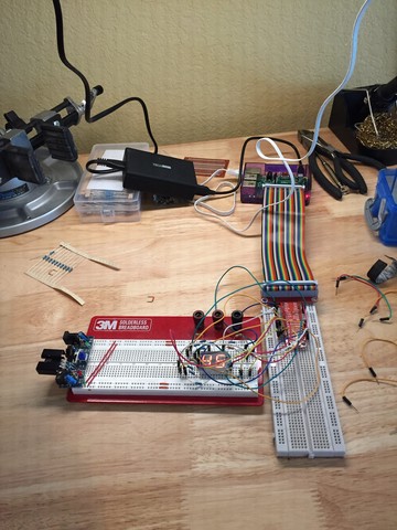
Most of my various projects have a purpose behind them. Home automation, various system administration projects… Even the TuneConsole had a useful, everyday purpose. In fact, I can’t think of a project I’ve done that doesn’t have a purpose.
Perhaps it’s time I try my hand at art?
A display like this has very little practical value in the modern age. LCDs are easy to deal with, or e-Ink, or any number of other things. And that’s assuming you’re not just sending stuff directly to your phone!
As art, though? That has potential.
It’s too bad I’m not really an artist…
…but I might as well give it a shot, right? The goal will be simple: build a little display, make it artsy, and put it on the internet. Spend as little effort as possible making it happen.
Piece of cake!
Wiring Stuff Up
The idea is pretty simple, to the point that I actually drew the schematic after the fact. These displays are common cathode, meaning that each of fourteen segments (plus the decimal point!) has a discrete anode pin, while all of the cathodes for those segments are tied together. Since these are two-digit display units, two cathode pins are offered: one for each digit.
With two digits per unit, six units will fit perfectly on a 60 column protoboard, so that’s twelve digits.
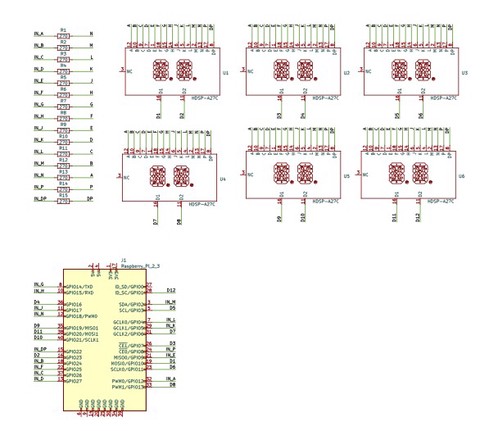
So how do we wire twelve digits, each of which has 15 discreet segments (hah! decimal point!), for a total of 180 individual LEDs, to a machine that only has a 40-pin header for expansion?
Yeah, you’ve probably guessed. Multiplexing is our friend here.
We’ll just group the segments together and connect each segment to a GPIO pin. So, for example, the segment A anode from every digit (that’s the top bar if you were wondering) will go to GPIO 12 on the Raspberry Pi. Why GPIO 12? Well, that’s just where it was convenient to put it. Each segment will get a different GPIO, and which one will largely be dictated by where the wires fall.
So we have fifteen segments connected to GPIO pins, and we’ll also connect each digit’s common cathode to another unique GPIO pin.
“But wait a minute!” some of you are saying. “That’s twenty-seven GPIOs! The Raspberry Pi only has twenty-six!”
There are twenty-six generally available GPIO pins on the Pi, yes. There are, however, also an additional two – GPIO 0 and 1 – that are normally reserved for reading the hat EEPROMs. Since we’re not actually a hat, and there’s no active electronics on this thing (depending on how you define “active”), we don’t care about that. We can just go ahead and usurp them for our own evil purposes, and it really won’t affect anything.
Which means we have just enough GPIOs; we even have one to spare!
The Physical Plant
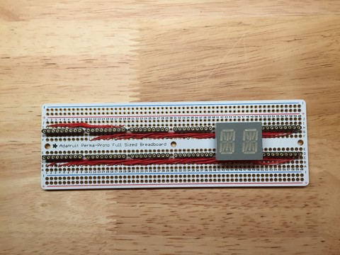
Okay, so we know how we’re going to wire it. The catch here is that with six double-digit display units on the protoboard, there is (literally!) no room for anything else. And that’s a problem. See, I forgot about the current limiting resistors we need between the Pi and all those segments.
What we need is easy enough: just stick a resistor between each collection of anodes and the GPIO pin it connects to. Testing and tinkering led me to a value of 270 ohms; this is a decent compromise between brightness and the maximum current the Pi can safely supply (works out to a maximum of ~75mA per digit I believe, which is on the edge of what a Pi can provide from the onboard regulators based on what documentation I could find).
With all our space taken up by displays, though, where are we going to put those resistors?
Time to introduce a second board. That will also allow us to add a socket so we don’t have to hardwire the connecting cable to our little toy. Really, though, that’s just a bonus.
Esoteric Methods
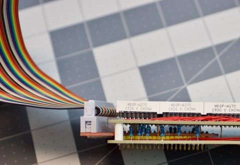
Another thing I’ve been fascinated by is so-called “Cordwood Construction”. Basically, three dimensional construction on multiple boards, where components can stretch between boards. It’s pretty neat looking, turning our toy into a sandwich with the layers supported by the components themselves. While there are far more impressive examples out there, I thought this was pretty good for a first try.
And yes, it was very fiddly getting the components all lined up correctly in their proper places. Do not do this if you have no patience!
The resistors and a few other raw links provide some stability, and then I added four heavier-gauge wires at the corners to give it a bit of strength. You can’t see those, though; they pass through the middle of the little plastic standoffs.
In the end, though, you have fifteen resistors and a bunch of wires, all sandwiched between two Adafruit-supplied protoboards, with the socket from a Pi breakout board sticking out. All in all, it’s a pretty neat look in my opinion.
Going On An Adventure
Okay, so we have a little device that we can plug into our Pi. The next step, of course, is to light it up and see if we can make it say something. Should be easy, right?
Actually, it kinda is.
I’ve been learning Go lately, and I’m really enjoying the language. Needless to say, I want to see how viable it is on a Raspbery Pi, and it turns out that the answer is “very”. The only issue I have is that I can’t get the latest version of the compiler (seems Raspbian only has up to 1.15), so I have to cross-compile.
I’m way too lazy to build and install my own compiler, or track down more recent packages for the Pi. Luckily, Go makes cross-compiling easy; just set a couple of environment variables.
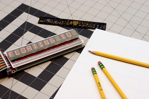
The application is simple enough. Grab a message off a message queue, and put it on the display. Wash, rinse, repeat. No problem, right?
The core of the app loops over each character in the display, pulsing it on for a brief while. It does this fast enough that the human eye will perceive it as a solid, persistent display.
For each character, it looks up a map of which segments should be lit. For each lit segment, the corresponding GPIO is set high if the segment should be lit, or low otherwise. Then the corresponding cathode for that character is briefly set low.
This is the correct configuration for current to flow, and results in our little LED segments lighting up as specified for that character (we’ve initialized the display so that, by default, all the cathodes are set high, preventing current from flowing through the other digits).
It does this repeatedly, fast enough that it can make a message appear. Add a bit of sugar to make it useful (namely, picking up messages when they appear on the queue), and poof. Nifty display!
This is, of course, extremely wasteful. It chews through between five and ten percent of a CPU core, constantly, just to keep the display fed. It could be optimized (eg. skipping ‘spaces’, etc.), but for now… it’s just an art project, right?
Optimizing art often misses the point.
Hey! It’s a great excuse for my laziness!
In any event, we have a working display toy that can take messages in and put them on the old-school 14-segment alphanumeric display.
What now?
The Whole Package
So now I have a display wired up to a Raspberry Pi. It can take messages over a wireless link and display them. But it’s just pieces laying on the table. And I haven’t really accounted for anything practical like, you know, mounting the thing. So what to do?
The project sits and gathers dust for a while. I have no idea.
Eventually I end up at an art supply store; I want to take some photos and I need a good backdrop. I have an idea of what to use for that, so I go get one.
And art supply stores are dangerous.
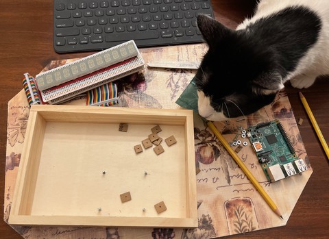
The place is interesting, and I end up wandering the whole store looking for inspiration. I finally walk away with a small “plaque” that I’ve decided I can abuse, along with a nifty little mini-easel. They were practically made for this!
A few holes, some bits of cardboard, a few bolts, and a curious kitty later, and I have something that can hold my little pi-and-display combination. The cardboard is because I don’t have any standoffs to use for mounting the Raspberry Pi.
Well, actually, I have the standoffs; I just don’t have screws that will fit them.
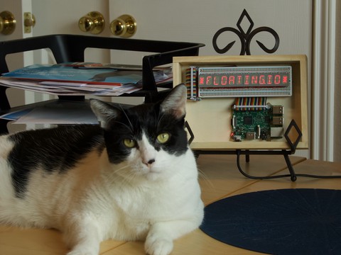
So a few bits of cardboard punctured by a multimeter probe will work just fine to hold the Pi at the right height, I suppose. Oh, and a strip of cardboard to go between the display board and the cable that runs underneath it.
Yeah, I forgot that the first time, and the results were rather interesting, and not fun to debug. The pins on the bottom of that Pi GPIO breakout are sharp!
Screw the whole mess together with a few cheap nuts and bolts, and voilà!
We have a toy!
The Final Goal
Okay, so I have my toy. It looks vaguely like art. It works. But now I need to meet the final goal: hooking it up to the internet!
Because everything needs to be hooked up the internet, right? Isn’t that what IoT is all about?
Well, that’s easy enough to do. I’ve spent a lot of time recently fixing up my web site, and thus I have all the pieces of the puzzle I need already in place. A custom shortcode for Hugo, a bit of javascript, and a new (and very simple) module for my app server, and now you can try it out:
Yup. That’s actually live and will send messages to my new toy.
If you don’t believe me, well, it’s a very underutilizied Raspberry Pi, so I hooked a webcam up to it. Now you can click below for the live stream (about ten seconds latency, but I’m far too lazy to try to make it any better than that):
Not sure how long I’ll leave that running, but we’ll see. It amuses me, though, which is kinda the point! Sorry about the small size, slow framerate, and low bitrate, but… bandwidth costs money, y’know?
And now I’ve met my goals. I have a nifty piece of art that displays messages from the internet. And with bonus points: the internet can see it happen!
(NOTE: The video is very experimental. Very. Haven’t spent much time sorting it out. I’ve already spent far more time on this presentation than I did actually building the thing, so the video is what it is, and may go away if it proves problematic! If you have problems viewing, try reloading the page…)
The End
It always feels great to finish a project, and this is no exception. That actually surprises me given the useless nature of it but hey, I’m not complaining!
Of course, it may also have to do with the fact that it gave me an excuse to set up a system for documenting my projects. This was holding me back before; WordPress could do it, but not the way I liked…
You can find more about the project right here, or by clicking the project link up at the top under the post date. Future projects and build logs will work similarly.
But I digress.
Art is fun, and so was this.
I’m thinking about setting a goal for myself: one useless bit of techno-art every quarter or some such. That would be fun, wouldn’t it? Of course, I’d have to figure out how to get the creative juices flowing more regularly since this isn’t my normal cup of tea.
Something to think about…